In this blog You can see Electronic door lock system, where is used PIC microcontroler 18F45K20 and button matrix with 12 buttons (3x4).
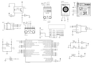
Here is the electrical scheme of this project:
There is 3 columns and 4 rows, 4 LED's (green) for indication door open (correct password) and 4 LED's (red) door not open (incorrect password). Password consisting of 4 digits (4 numbers), and You checking is Your password correct or not with one button (Provera (Check)).
Also there is an LCD for showing messages. Messages which it showing are:
- "Insert password"
- When You inserting password, mesage is "Inserting pasword" (x4)
- If You insert 5-th digit of password You'll get a message on LCD "Wrong password" and after few seconds on LCD is new message "Try again".
- When You insert correct password You'll get message "Door open".
You inserting password
"Wrong pasword"
Success! Door is open :)
Also there is an DC motor, which purpose is, when door is open by password, to unlock door lock system.
Link for simulation of this Electronic door lock system.


