понедељак, 30. април 2018.

Electronic door lock


       In this blog You can see Electronic door lock system, where is used PIC microcontroler 18F45K20 and button matrix with 12 buttons (3x4).


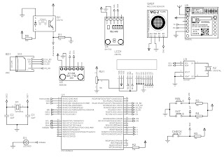
            Here is the electrical scheme of this project:


          There is 3 columns and 4 rows, 4 LED's (green) for indication door open (correct password) and 4 LED's (red) door not open (incorrect password). Password consisting of 4 digits (4 numbers), and You checking is Your password correct or not with one button (Provera (Check)). 

             Also there is an LCD for showing messages. Messages which it showing are:
  1. "Insert password"
  2. When You inserting password, mesage is "Inserting pasword" (x4)
  3. If You insert 5-th digit of password You'll get a message on LCD "Wrong password" and after few seconds on LCD is new message "Try again".
  4. When You insert correct password You'll get message "Door open".
Next pictures presenting this messages:

You inserting password

"Wrong pasword"

Success! Door is open :)

                Also there is an DC motor, which purpose is, when door is open by password, to unlock door lock system.

Link for simulation of this Electronic door lock system.

недеља, 29. април 2018.

Digital clock with Temperature information

       In this article, you can see how to make Digital clock using PIC microcontroller and 7 segment displays with temperature info on it.

       Realized digital clock you can see below:


       Electrical scheme of digital clock is below:


       How you can see, 7 segment displays are controlled with shift registers 74HC595. For control this shift registers, you need only 3 pins (one for Data (DS), one for Shift clock (SH_CP) and one for Storage clock (ST_CP)). Also you need to wire EN and MR pins of shift registers to GND and Vcc, respectively, to allow shift registers to work properly.

       Data is transferred from the one shift register to another through Q7' pin (view in data sheet).

       Information of temperature coming from temperature sensor DS18B20 (Dallas semiconductor) - one wire protocol. For measuring temperature it's using one pin (bidirectional) with pull-up resistor (4.7 k - 10 kΩ).

       How it works you can see here.

       For more information contact me at djordjevicpoljak@gmail.com

       Enjoy!

среда, 18. април 2018.

Weather station - Data Logger

          In this article, you can see how to make Weather station device - Data Logger for measuring and storing measured values.

          It can measure atmospheric parameters like:

               - Wind speed [m/s] - [km/h],
               - Atmospheric Pressure [mBar],
               - Temperature [℃] - [℉],
               - Humidity [%],
               - Light intensity [lux],
               - LPG detection [%] and
               - Altitude [m].

          Weather station - Data Logger can be used in Botanical Garden, Libraries, Hospitals, Mines, etc, not only in Agriculture.

          All values of measured parameters can be stored on few medium like:
     
              - SD (Security Digital) card,
              - SMS (Short Message Service),
              - IoT cloud ThingSpeak

          Block diagram of Weather station is below:

          Electrical scheme of Weather station is posted below:

          When Weather station - Data Logger is start-up, first you need to set Language of device, it can be:
               - English,
               - Serbian,
               - Deutsch and
               - French.

         After that, you have to set actual time and time when weather station to stop the measuring.
       
         Next is settings of the Name of file if you storing measured values on SD card, reason of that is you doesn't need to delete previous measurement.
       
         When you storing measured values on SD card, and you are not near the device, and you need to know when pick up the device at the end of measuring. In that case, you need to set number of cell phone where you can receive SMS like notification of end of measuring.

          After that settings, on LCD display you get message of starting measuring and storing on SD card.

          When measuring is done, GSM SIM800l module send SMS on number you set before.

          Realized Weather station - Data Logger on protoboard is on this picture:


How it works you can see here.

Enjoy!

петак, 23. март 2018.

LED propeller clock

In this post you can see very interesting LED propeller clock, which is my final exam on Faculty of Elevtronic Engineering in Niš, Serbia. Also, there is scheme of propeller and base and radio community, which is used to transfer data from base to propeller. With that community we can send information about time and pictures (monochromatic (79×79).BMP). Microcontroller on propeller is PIC18F2515 (SMD).
This is 3D layot of propeller PCB (maded in Proteus Profesional – ARES PCB Designer).
Scheme of this propeller is on this picture:
This propeller have 40 LEDs (3mm), RTC pcf8563 (for time and date) and flash memory. Radio community receiving information from base and send it to microcontroller, where that information is processing. Next step is send processed information to shift registers (74HC595 on PCB on bottom layer), and finally that information go to LEDs.
Base have three parts. First, power supply, maded like air transformer (primary coil – static coil, have above 200 turns, secundary – rotary coil above 400-500 turns), and on propeller we have is 12VDC. Scheme of power supply:
Power supply
Power supply
Secound, there is motor speed control, where we can control speed, and make better view of pictures on propeller. Scheme of it:
Speed motor control
Speed motor control
And last part of base is data transfer:
Data transfer
Data transfer
When all work, you can see something like this:
IEEE logo
IEEE logo
Faculty of Electronic Engineering logo
Finalized LED propeller look like this (there is a few pictures (PCB, mask, propeller, base…)):
Mask - top (right) and bottom (left)
Mask – top (right) and bottom (left)
Flash memory
Flash memory
LED propeller clock
LED propeller clock
How it working, you can see here

уторак, 30. јануар 2018.

Bluetooth robot

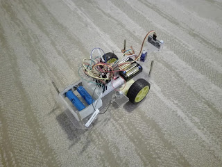
      In this article, you can see my Bluetooth robot. It used for teaching students how to control Bluetooth module (HC-05) using Android application. Bluetooth module is controlled by PIC microcontroller PIC 16F628A, which control motor driver L293d which control 2 DC motors.


      Chassis is made of plexiglass and at next picture you can see dimension of it.


      Electrical circuit of Bluetooth robot you can see at next picture.


      Android application I made using MIT App Invertor 2. This app maker it's easy to work then Android Studio (for someone who don't have knowledge about Android programming in Android studio). Layout of application for Bluetooth robot is at next picture.

   
     As you can see, there is 4 buttons for any direction, and there is a button for connection with Bluetooth (robot) module. Before you want to control your robot, you need to pair your smart phone with HC-05 Bluetooth module (Settings -> Connectivity -> Bluetooth -> Found new device). Afther that, there will be shown window where you need to write Pin code for pair module and phone (1234 or 0000, which depends of Bluetooth module).
     After that, you can run application, and pick button Connect, after that will be open window where you can chose which module you want to connect with (HC-05). If everithing is OK, button name from Connect will be change to Connected. Now your application is ready for control robot.

     Lets we back now to PIC microcontroller and how to write code to control robot with received data from Android application.
 
    Compiler I used for writing code for microcontroller is Proton IDE, it's Basic language. In code you need to set U(S)ART for receiving data from Bluetooth module, test received data and if condition is OK, drive robot. In algorithm you can see steps through code:


     First set U(S)ART:
- Baudrate set to 9600
- Set RX and TX register (RCSTA = $90 and TXSTA = $24 (value of U(S)ART registers)
- Set to Clear Buffer after every received data

    After that, declare variable where microcontroller will put received data. Variable type depend on what you want to send from application. What that mean? If you want to send something like "Forward", you can't use integer type (in Proton Basic that is Byte), you need to declare it like Char (Word in Proton Basic). In other case, if you want to send "0" - "255" you need to use integer type (Byte).

    Now we have to check are we receive some data. If we are, now we check is received data correct, does we have that in condition. If condition is OK, microcontroller go to part of code where we define in which direction we want to drive robot.

    For receiving data in Proton Basic you can use HSerIn where you have to set few parameters, Timeout (how long microcontroller wait for data (in miliseconds)), Timeout_label (where code executing go if there is no data) and (modifier) variable where microcontroller put received data. HSerIn command looks like:

          HSerIn Timeout, Timeout_label, [Modifier Variable]

For example:

          HSerIn 50, Main, [Dec Variable]

In If command we check is received data equal to any of declared condition:

          If Variable = ??? Then
               xxx xxx
               xxx xxx
               ...
               xxx xxx
          Endif

Checking for condition is in endless loop, thats mean you can drive your robot until you don't empty batteries.

Realization of Bluetooth robot you can see here.

For code (.hex) and application (.apk) file contact me at my e-mail: djordjevicpoljak@gmail.com

Enjoy!